ADVANCED VEHICLE TECHNOLOGIES, Inc.
AVT-440
Hardware Revision Descriptions
Order Number Descriptions
Photos
Updated: 13 November 2024
Notes
General Description
DSI3 Bus Master, two channels.
PSI5 Bus Master, two channels.
Communication to client computer: Ethernet.
Hardware Configuration
Only one configuration option is available.
It is the AVT-440-006.
This includes the AVT-440 custom PC board housed in
the Netburner PK70 unit configured with the latest AVT-440 firmware.
PC Board Revision
PC Board Revision Notes
The revision of the PC board is noted in copper on the bottom of the
board.
It only changes when the board is redesigned.
The "as built" revision is noted in the white "rev" block on the top of
the board.
PC Board Revision A
October 2018.
Original board design.
Released for production as no changes were required.
PC Board Revision B1
19 July 2019
Added PSI5 transceiver device and related circuitry.
Removed the MOSFET switch for the VDSI bus supply to the DSI3 Bus Master
device.
PC
Board Revision B2
~ 1 August 2019
A hand modification to the original rev. "B" board.
Remove pin # 21 from J1. This disconnects CPU signal PCS1 from the
PSI5 transceiver TRIG input.
Install a small wire from J1 pin # 25 (signal PFECI2C0) to the hole on
the PC board for J1 pin # 21. This connects CPU signal PFECI2C0 to
PSI5 transceiver TRIG input.
PC Board Revision C1
31 August 2019
Correct the signal change described above.
This results in the removal of wire via 8 (WV8).
No modifications to the board.
PC Board Revision C2
10 November 2019
Hand modified the board to work with the external AVT-441 "DSI3 Boost"
board.
Refer to the modification document for details. (Request a copy
from the factory.)
PC Board Revision D
~5 December 2021.
Changed the 4 MHz clock device. I need to build a batch of boards.
At present there are terrible shortages of electronic components.
I could not procure the original clock device, so I changed the
board layout. The new clock device is slightly smaller and uses
(what I hope) is a more standard footprint.
Also included in this revision are changes to the board to incorporate
the hand modification changes to "C2" needed for the AVT-441 "Boost Device".
PC Board Revision F
~23 June 2023.
I modified the footprints for several devices.
I made the pads larger and so that they extended beyond
the edges of the devices. This should make assembly
somewhat easier and make the solder joints more visible
for inspection and improve assembly quality.
Refer to the change list in the project files for device list.
Or, compare the rev. "D" with rev. "F" checkplots.
Assembly "F1" refers to the assembly using the original parts list.
Assembly "F2" refers to the fact that the PSI5 voltages 7.4 and 8.1 were
tuned. Thus, R25 (for 7.4 v) and R27 (for 8.1 v) may be different than
specified in the parts list.
The "tuning" procedure involved replacing R25, R26, R27, and R28 with 0.1 % tolerance
resistors. Then the reference voltage was computed. Then new R25 and R27
values were computed. Then those resistors were replaced. The goal was to
obtain output voltages as close as possible to 7.4 and 8.1 vdc.
PC Board Revision xxx
dd mmm yyyy.
xxx.
PC Board Revision xxx
dd mmm yyyy.
xxx.
Order Number
Descriptions
AVT-440-006 : Custom AVT-440 board, installed in Netburner PK70
unit.
Status: Not normally a stock item. Lead time approximately 3 weeks
(depending on many factors).
Contact factory for current lead time.
Photos
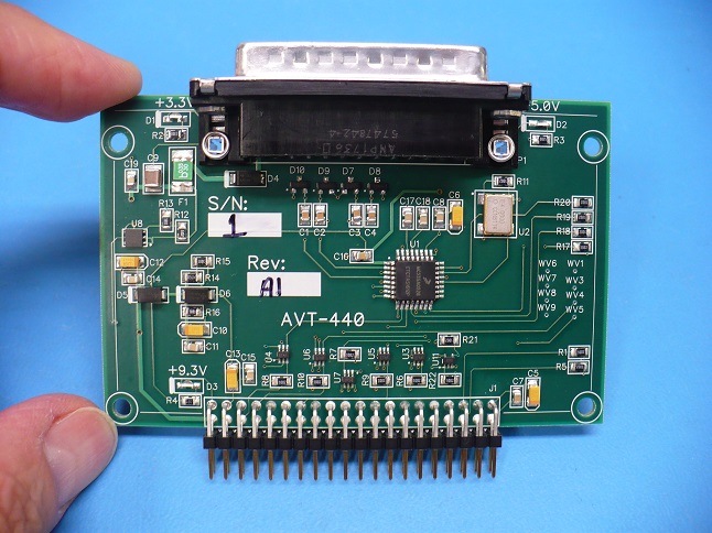
AVT-440
rev. "A1" board only, top.
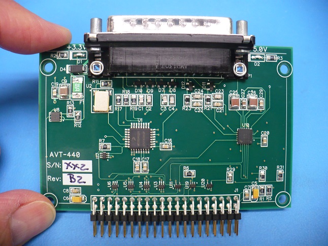
AVT-440 rev. "B2" board only, top.
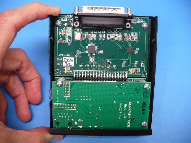
AVT-440 rev. "B2" Board Mounted in PK70.
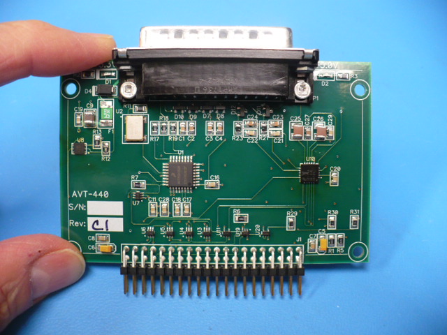
AVT-440 rev. "C1" board only, top.
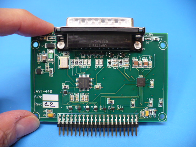
AVT-440 rev. "C2" board only, top.
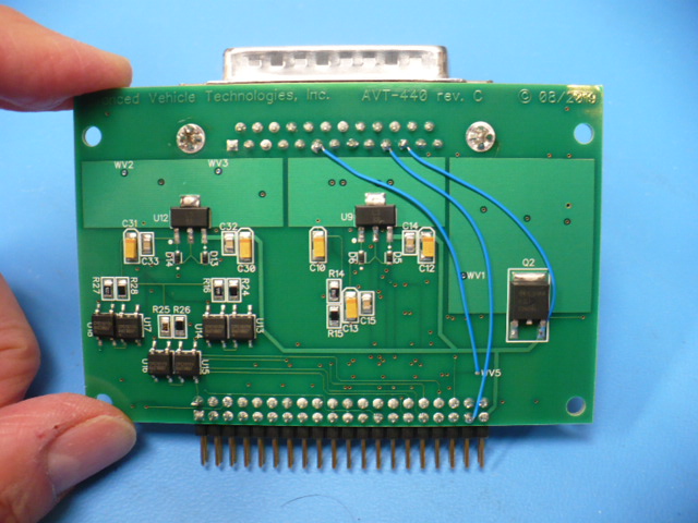
AVT-440 rev. "C2" board
only, bottom. Modifications shown.
Site
Map


